5.1 The controller
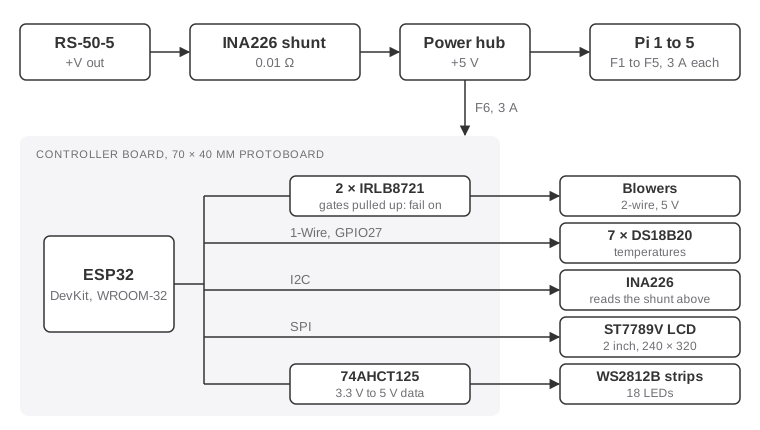
One ESP32 does four jobs: it reads the temperatures, it sets the fan speed, it drives the screen and it runs the lights. It sits on a 70 × 40 mm protoboard with two MOSFETs, a level shifter and a handful of connectors, and the same board goes in either design.
Driving 2-wire blowers
The GDSTIME blowers have two wires: power and ground. There's no PWM input and no speed output, so the only way to slow one down is to give it less voltage.
Each fan runs from 5 V through an IRLB8721 logic-level MOSFET on its ground side. The ESP32 switches the MOSFET at 25 kHz, above hearing, and a 100 µF capacitor across the fan smooths the pulses into a steady, lower voltage. A 1N5819 diode across each fan takes the kick when it switches off.
The fans fail safe. Each MOSFET's gate has a 10 kΩ pull-up to 3.3 V. While the ESP32 is booting, resetting or hung, its pins float, the pull-ups win, and the fans run flat out. Only working firmware can slow them down. The worst a firmware bug can do is make the fans loud.
The fan curve
Every 5 seconds the firmware takes the hottest of the five board exhausts:
So the fans sit at 40% until the hottest exhaust passes 30 °C and reach 100% at 45 °C. 40% is the floor because a 5 V blower may not start below about 35%. After every boot they run at 100% for 2 seconds, just to get them spinning.
If any exhaust goes over 55 °C, the power supply's chamber goes over 60 °C or a sensor goes missing, the fans go to 100% and the lights go red. A missing sensor counts as hot.
There's no tachometer, so a stuck fan can't report itself. It shows up as one half of the box running hotter than the other, and the screen flags a difference of more than 8 °C.
Sensors
Seven DS18B20s share one 1-Wire bus on GPIO27, with a 4.7 kΩ pull-up. They read to 0.0625 °C at 12 bits.
| Sensor | A2 | B2 |
|---|---|---|
| Intake | In the duct, at the foot | In the plenum, at the blower outlets |
| Board 1 to 5 exhaust | At each tray's side vents | Under the top grille, over each channel |
| Power supply | In its chamber, at its vents | The same |
The boards know their own SoC temperatures. They don't need to tell the ESP32 for the fan control to work, but they could publish them over MQTT later for the screen.
Measuring power
An INA226 sits between the power supply and the hub, so it sees everything: the boards, the fans, the screen and the lights. It reads the bus voltage and the current through a shunt, and power is the product.
The catch is the shunt. Most INA226 modules come with 0.1 Ω, which reads to only 0.8 A. I need one with 0.01 Ω (marked R010), or an external 0.01 Ω 2 W resistor. That reads to 8.2 A, above the worst case of 7.5 A, and at 7.5 A it drops:
So the supply goes up from 5.20 to 5.25 V to keep 5.08 V at the boards.
The screen
A 2 inch, 240 × 320 IPS module with an ST7789V, on SPI. Landscape, white and amber on black:
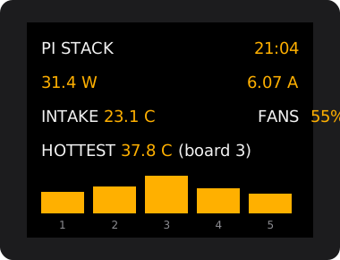
The backlight is on a PWM pin, so it drops to 15% at 22:00 and comes back at 07:00.
Lights
WS2812B strips, 18 LEDs in all. Each LED can draw 60 mA at full white, so 18 could take 1.1 A. The firmware caps the strip at 40%, which keeps it under about 0.45 A. The ESP32's 3.3 V data goes through a 74AHCT125 to 5 V, with a 330 Ω resistor in the line and 1000 µF across the strip's supply.
The default is warm white. One effect splits the strip into five and shows each board's exhaust as a colour, from blue at 25 °C to red at 50 °C.
Power budget
| Load | Current |
|---|---|
| Five boards, flat out | 6.50 A |
| Two blowers, full speed | 0.28 A |
| ESP32 with Wi-Fi, peaks | 0.25 A |
| LCD with backlight | 0.06 A |
| LEDs, capped at 40% | 0.45 A |
| Total | 7.54 A of 10 A |
Firmware
It's ESPHome: one YAML file, firmware/pistack.yaml. Every part here has a ready-made ESPHome component (dallas_temp, ina226, ili9xxx for the ST7789V, esp32_rmt_led_strip, LEDC outputs), so the only code is two short lambdas, one for the fan curve and one for the screen layout. It also puts every reading on the network for free.
It compiles on ESPHome 2026.10.1 with no warnings, and uses 54% of the flash and 28% of the RAM. The first validation caught two things: clock and alarm are reserved IDs in ESPHome, so they're now sntp_time and over_temp. It hasn't run on a real ESP32 yet, and the sensor addresses are placeholders until I flash it once and read them from the log.