8.6 Exports and assembly
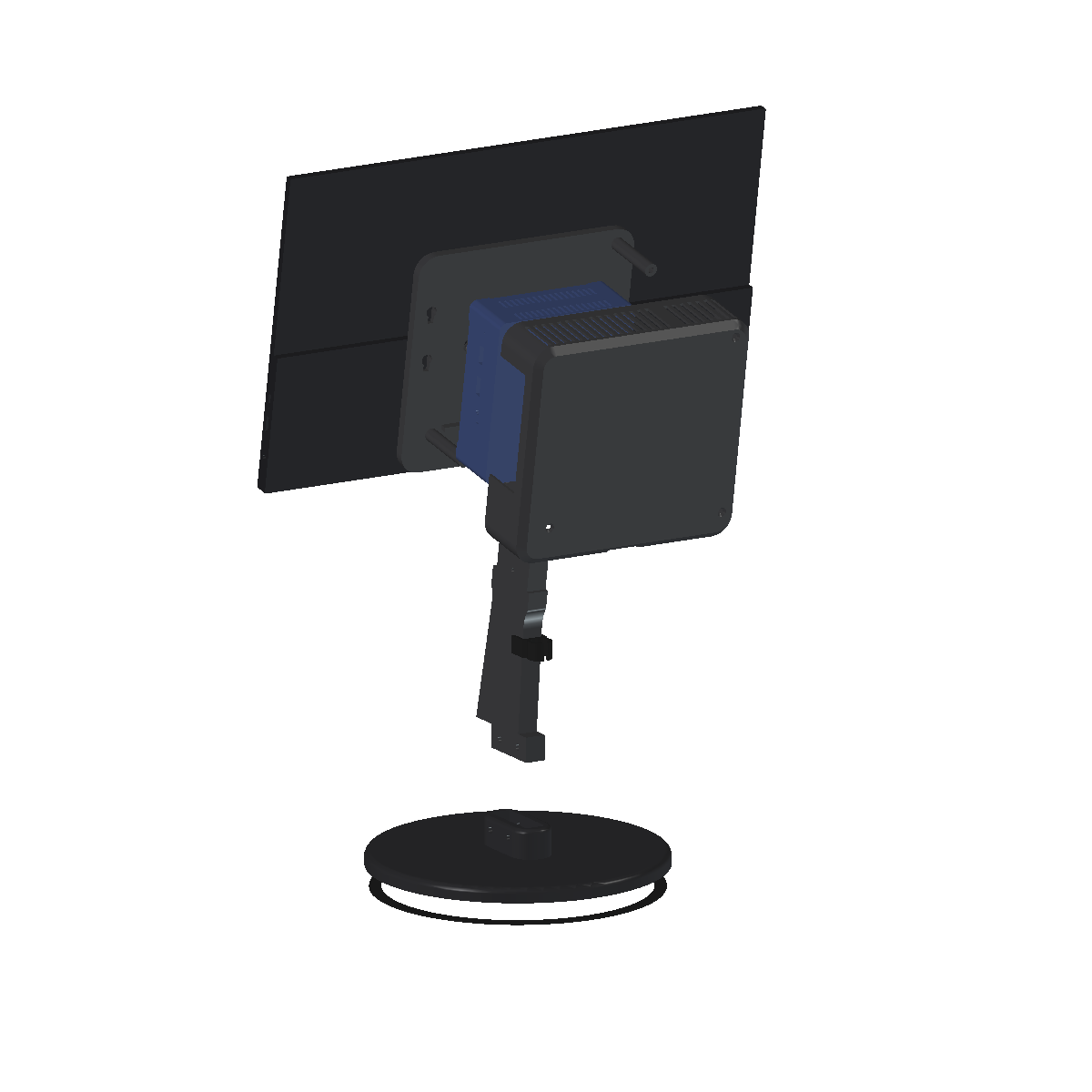
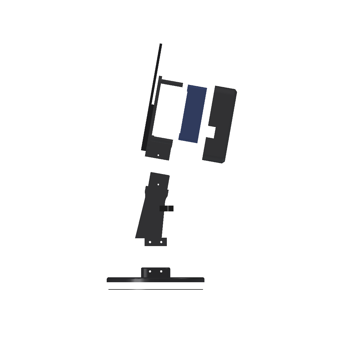
The last step before printing was to get the design out of FreeCAD intact: a STEP file for every printed part, a STEP assembly for each variant with the monitor and the PC, and an assembly sequence. Two hidden faults turned up on the way. Both parts looked fine where I normally look.
Fault 1: STEP lost a third of a fin
E3's fin was a valid solid in FreeCAD. Read back from its STEP file, it was five open shells with 36% of its volume missing. The STEP writer had dropped the faces made by extruding 2D offset curves, which is how every fin profile is built.
The fix: convert every part to NURBS before export. The export script now reads every STEP file back and checks its solid count and volume against the model.
Fault 2: the slicer repaired a broken mesh in silence
E3's fin STL was not a closed solid. The A1 slicer repaired it without a warning, so the slice looked clean. The cause was the 2D offset again: makeOffset2D left edges of 0.00001 mm in the sail's profile, and those extruded into sliver faces.
The fix: drop edges under 1 µm from each profile before extruding. The export script now stops on any STL that is not a closed, manifold solid.
The lesson extends 8.3: the slicer is a check, but not a complete one. It reports some faults and hides others. Check each export file directly: read the STEP back, and test the STL for closure.
All 12 PLA parts were re-sliced. The structural figures did not change, and the times moved by a few minutes:
| E1 Arc | E2 Column | E3 Sail | E4 Wall | |
|---|---|---|---|---|
| Whole device: time, PLA | 9 h 47 min, 398 g | 8 h 58 min, 357 g | 9 h 55 min, 408 g | 7 h 6 min, 267 g |
Assembly sequence
- Press the three M3 heat-set inserts into the carrier's pillar tops, and the TPU pad ring into the foot's underside.
- Screw the carrier to the monitor's VESA inserts: 4 × M4 × 10 countersunk, flush.
- Screw the two shoulder screws into the PC's base inserts. Offer the PC to the carrier, heads through the keyhole holes, and slide it 8 mm down onto the ledge.
- Plug in the PC's rear cables. Lead the mini HDMI and USB-C out of the bay's side exit to the monitor, and the rest down through the bay's floor.
- Fit the shell over the PC, its notch round the collar, and screw it on from behind: 3 × M3 × 8 countersunk.
- Drop the fin's tenon into the foot's plinth and bolt it: 2 × M4 × 40 with nyloc nuts. For E4, screw the wall plate to the wall first, then bolt the fin into its plinth.
- Lower the hub onto the fin's tongue until the shoulder seats on the collar. Push the M3 × 30 pin through and fit its nyloc nut.
- Clip the down cables into the TPU clip on the fin's back edge.
To take the PC out: pin out, lift the hub off the tongue, take off the shell, and lift the PC 8 mm. One VESA screw sits under the PC, so the PC comes off before the carrier.