3.4 D, Monolith
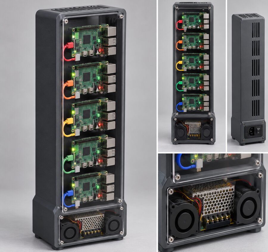
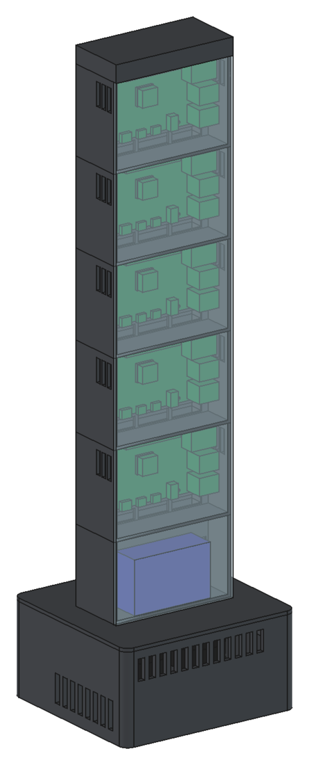
A tall slab of five stacked cells, every board face on behind one tall front panel, on a wider plinth. It's 531 mm tall. I've turned it down, but I applaud it.
The slab
The slab is 108 mm wide and 53 mm deep, and it's made of identical cells. Front to back, a cell is:
| Layer | Depth from the front |
|---|---|
| Perspex front | −3 to 0 mm |
| Air, then the board's components | 0 to 20.4 mm |
| The PCB's underside | 20.4 mm |
| Standoffs | 20.4 to 25.4 mm |
| Carrier wall | 25.4 to 27.4 mm |
| Duct | 27.4 to 47.4 mm |
| Back wall | 47.4 to 50.4 mm |
The board lies landscape, components forward, USB-C edge down. The right-angle plug hangs 14.3 mm below the board, so a cell is 2.5 mm of floor, 15 mm for the plug and 56 mm of board: 74 mm. Five cells, a 66 mm service bay for the power hub and a 15 mm cap make the slab 451 mm. On an 80 mm plinth, that's 531 mm.
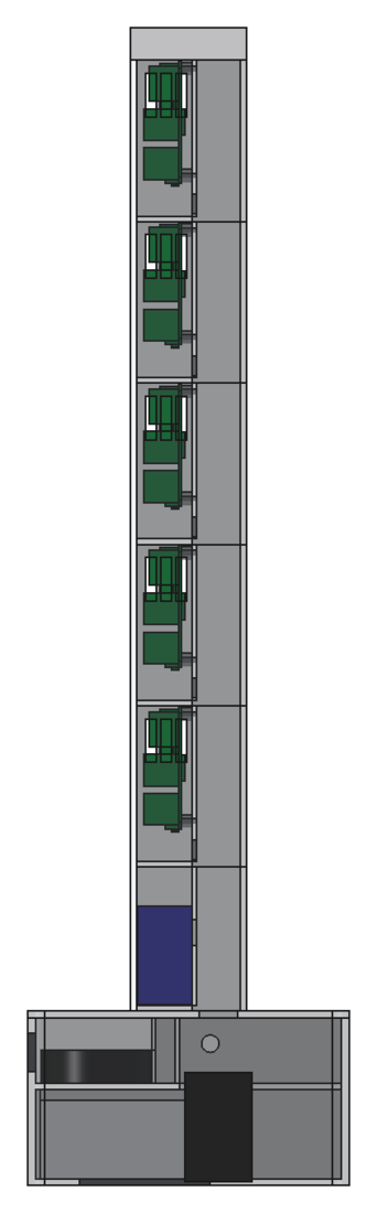
The duct runs up behind the cells. At the foot of each cell's carrier wall, three 28 × 9 mm slots let duct air into the cell. It rises over the board and leaves through three slots in each side wall at the top of the cell. So the boards are fed in parallel, like A. Each cell is about 1,090 mm² across with its board, the tightest of the four, and the air moves at about 0.37 m/s.
The cells are small identical prints, 108 × 50 × 74 mm, and a sixth cell would take a sixth board.
The plinth
The plinth is A's plinth turned round. The power supply lies flat with its terminals to the right, into the mains compartment. The inlet stands upright in the right wall, so its 47.5 mm length runs up and its body fits behind the terminal block. The blowers lie on a shelf over the supply, draw through the front grille and blow back into a plenum, which opens up into the slab's duct through a 74 × 17.5 mm hole in the deck.
Why it's out: balance
The first version had a 108 mm deep plinth. It passed the 10° test (it tipped at 15°), but the push at the top that tipped it was only 1.4 N. Deepening the plinth to 148 mm and centring the slab on it brought that to:
Still nothing. To resist 5 N at the top, the product of mass and lever has to be:
At 1.56 kg, the centre of gravity would need to be 173 mm from every edge: a plinth 350 mm across. Or I add mass low down. A 1 kg steel plate in the plinth floor (about 140 × 90 × 10 mm) lowers the centre of gravity to about 111 mm and takes the push to 3.2 N and the tip angle to 32°. That's what I was offered.
I don't want ballast in this. If it needs a steel plate to stay upright on the desk, it's the wrong shape. And 531 mm is just too tall.
What the checks caught
- The power hub ran 0.6 mm into the bay's carrier wall (1,890 mm³). It moved forward.
- A short wall at the end of the power supply sat 1 mm inside its lead space (72 mm³). It got trimmed.
Printing
| Part | Prints | Size (mm) |
|---|---|---|
| Plinth | 1 | 158 × 148 × 77 |
| Deck | 1 | 158 × 148 × 3 |
| Bay | 1 | 108 × 50 × 66 |
| Cell | 5 | 108 × 50 × 74 |
| Cap | 1 | 108 × 53 × 15 |
| Front (perspex) | 1 | 436 × 108 × 3 |
The joints between the stacked modules were never designed. They'd need a lip or a pair of dowels each.
What Claude kept from it
Claude flagged two ideas to carry forward: the face-on view, with five boards behind clean perspex and all their LEDs showing, and the stacked identical cells, which make room for a sixth board.