3.3 C, Pentagon Column
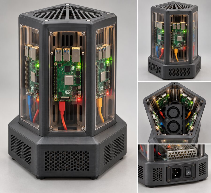
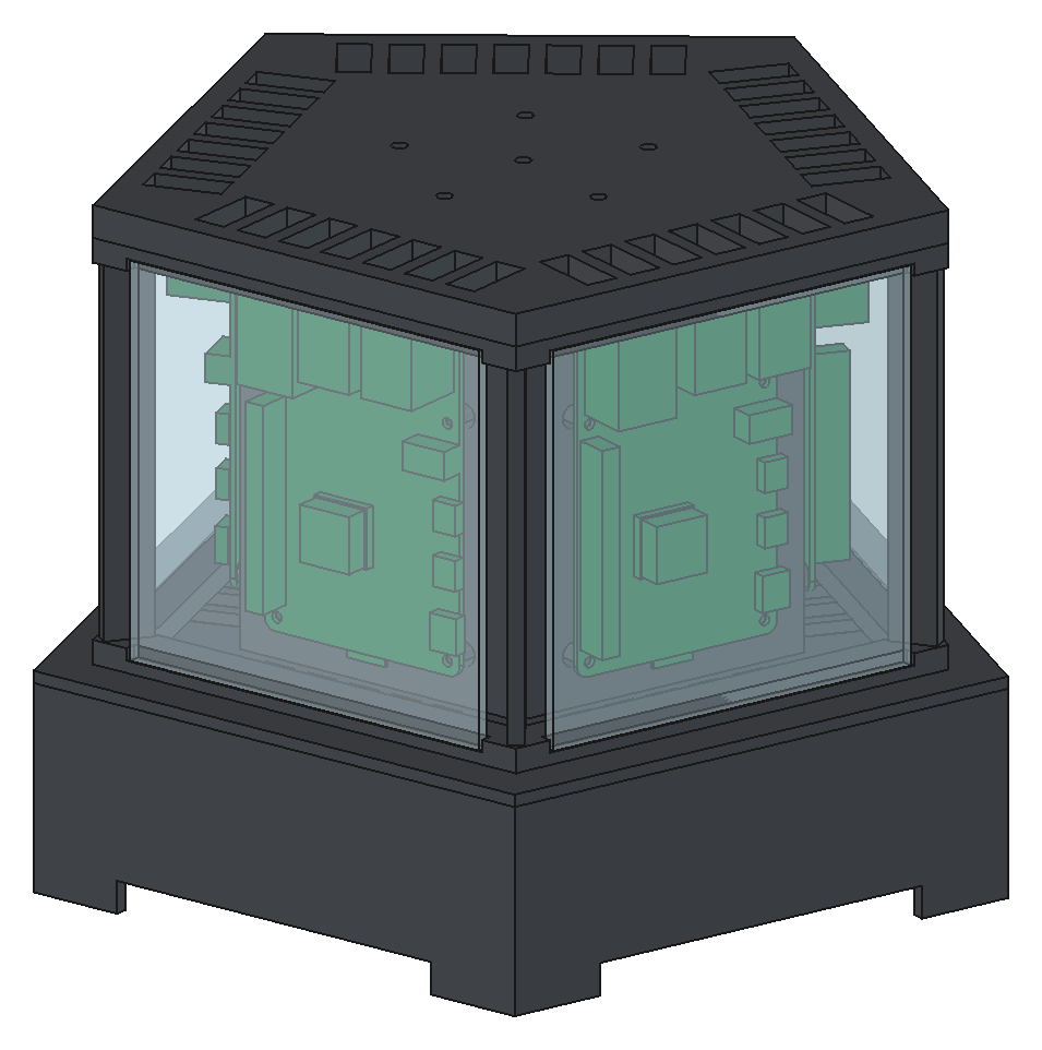
One board on each face of a pentagonal column, components facing out behind five windows. Walk round it and every board is face on. It's 223 × 212 × 166 mm.
Where the boards can go
A pentagon's faces meet at 108°, so boards on neighbouring faces close in on each other at the corners. Each board is 56 mm wide on its face, so half of it is 28 mm either side of the face's centre line. The corners of two neighbouring boards miss each other only if the boards are far enough from the axis:
That's for the PCB alone. The USB-C plug stands out sideways from one long edge, and it has to miss the next board's GPIO header, so the real minimum is more like 45 mm.
The boards ended up at 60 mm, for a different reason: the power supply.
The power supply in the core
There's no room in a plinth this size for a 99 × 97 mm power supply lying flat as well as two blowers, the inlet and the hub. Claude tried. So the supply stands on its end, terminals down, inside the column. The boards stand on the five walls of a printed pentagonal core, on 5 mm standoffs, and the supply lives inside it.
Standing up, the supply's cross-section is 97 × 36 mm. Its corners are 51.7 mm from its centre, so it fits any way round in a pentagon with a 53 mm inradius. The core walls are 53 to 55 mm out, the standoffs take the boards to 60 mm, and the components reach 77.4 mm. Then 3 mm of air, and the perspex at 80.4 to 83.4 mm.
The core is closed, so it's the mains zone, together with a compartment under it in the plinth. That compartment runs out to the inlet in the back-left face. Five 4 mm holes in the floor let a little plenum air into the core, up past the supply and out through the cap. The supply gets its own chimney, and no finger fits through a 4 mm hole.
The plinth is the plenum
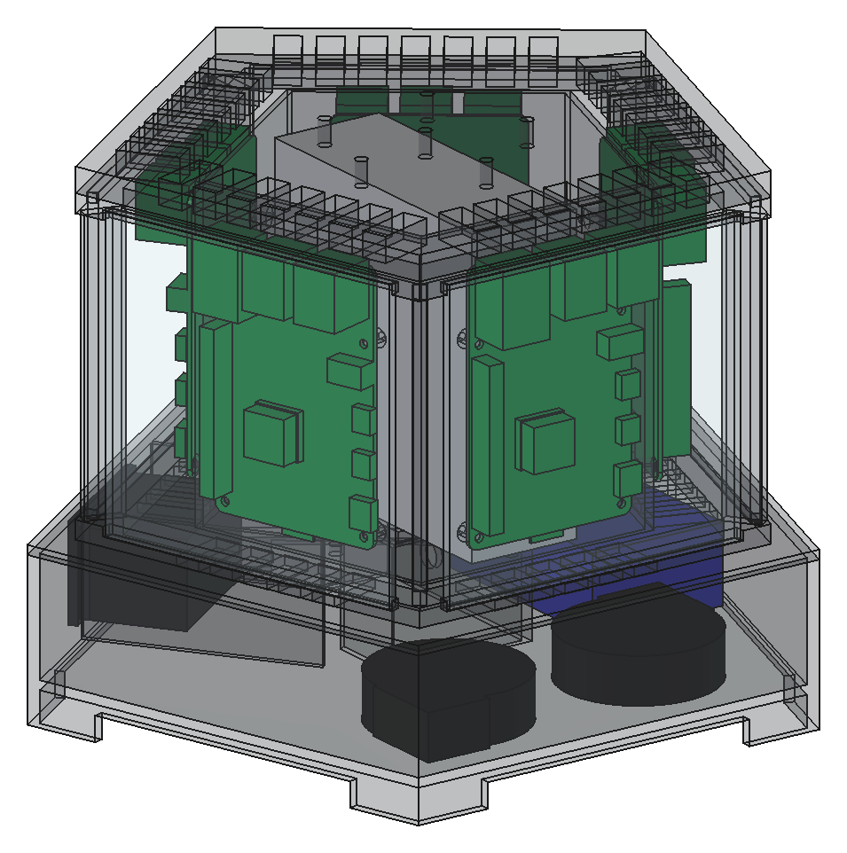
The blowers lie upside down on the plinth floor, each over a 30 mm hole. The plinth stands on five feet with 8 mm openings between them, so the blowers draw air from under the plinth and blow it straight out into the plinth itself. The whole plinth becomes the plenum, with no ducting at all.
The column's floor plate has five air slots under each board's cell. Air rises through them, up each face between the core and the window, over the board and out through slots in the cap. Each cell is about 1,430 mm² across with the board in it, and the air moves at about 0.28 m/s.
The power hub sits in the plenum on the right. Low-voltage parts are fine in the air path; the mains parts aren't, and they're all in the core and its compartment.
What the checks caught
The first run failed five times over with the same fault. The frame's five corner posts each overlapped a board's USB-C plug space by 43 mm³.
The posts were meant to start 72 mm out. But the posts run along the corners, and 72 mm along a corner line is only:
out along the face, right where the plug sits. The fix was to start the posts at mm along the corner line, which is 72 mm out from the face. Then they only hold the windows, which is all they're for.
The second fault didn't fail any check. The plinth (95 mm inradius) is wider than the column (83.4 mm), and the gap between them was open to the plenum. Half the air would have gone straight out of it. The floor plate now spans the whole plinth.
Printing
| Part | Prints | Size (mm) | Orientation |
|---|---|---|---|
| Plinth | 1 | 223 × 212 × 51 | Upright |
| Floor | 1 | 223 × 212 × 3 | Flat |
| Core | 1 | about 145 × 140 × 104 | Upright, 20 standoffs |
| Frame | 1 | 196 × 187 × 104 | Rings and posts |
| Cap | 1 | 196 × 187 × 8 | Flat |
| Windows (perspex) | 5 | 100 × 98 × 3 |
The plinth is the widest print of the project, 223 mm across, with only 27 mm to spare on the A1's bed.
Balance
1.42 kg, centre of gravity 87 mm up, nearest edge 83.8 mm away. It tips at 44°, and the push at the top is:
The most stable of the four.
Good and bad
- The five windows are all the same small rectangle, so the perspex is one cut size.
- The plinth as a plenum is simple and quiet.
- It's wide and squat. Making it taller means taller cells, and the boards don't fill them.
- The board screws go into the core walls, which bound the mains zone. M2.5 × 8 screws stop short of the inside, and the holes have to stay closed.
- Changing a board means lifting the frame off.