5.1 Carrier, spine and foot
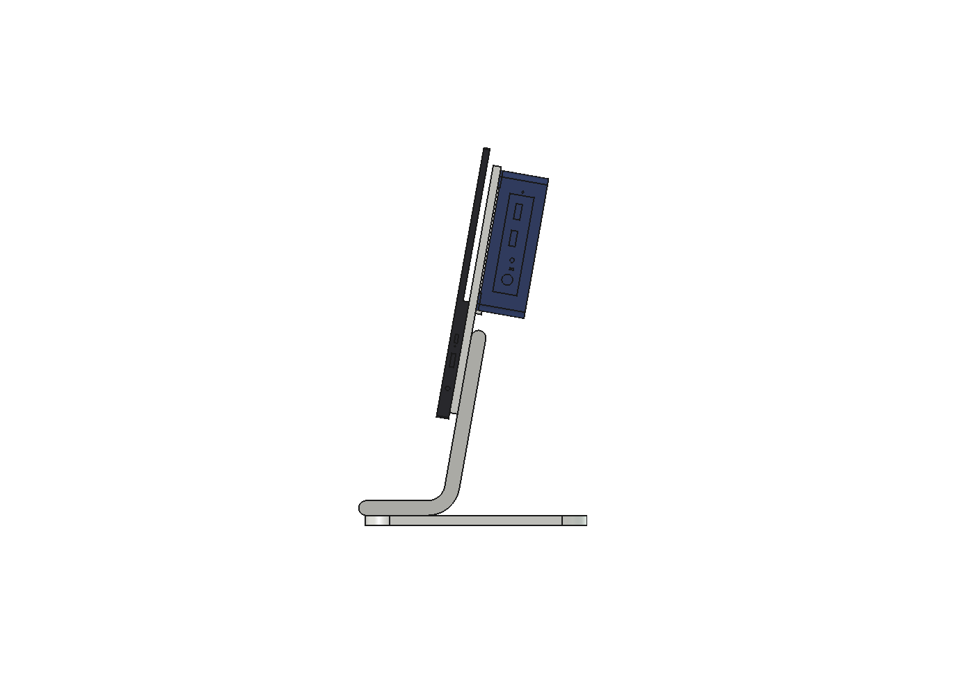
| Part | PLA | Joints | |
|---|---|---|---|
| Carrier, 110 × 204 × 6.5 mm plate with a ledge | Flat | 63 g | To the monitor: 4 × M4 × 10 countersunk from behind, flush. To the PC: two keyhole slots. To the spine: 4 M3 heat-set inserts |
| Spine, 60 × 12 mm, leaning back 10°, a 20 mm bend into a 50 mm pad | On its side, 60 mm width up | 66 g | 4 × M3 into the carrier over a 64 mm lap; 4 × M3 down into the foot |
| Foot, 200 × 180 × 8 mm, 20 mm corners | Flat | 124 g | 4 M3 heat-set inserts under the pad |
The VESA screws
The monitor's inserts give 3.6 mm of thread (3.1). An M4 × 10 countersunk screw (ISO 10642) is measured head included, so through a 6.5 mm plate it leaves 3.5 mm. Countersunk also means flush: my first layout used pan heads, and the upper two clashed with the PC and its ledge.
Hanging the PC with no tools
The PC hangs on its side on two shoulder screws (ISO 7379: 4 mm shoulder, M3 thread, 8 mm long) in its own base inserts. The shoulder seats on the insert, so the head stands a fixed 8 mm off the base: 6.5 mm of carrier plus the 1.4 mm the corner pads hold it off. A plain screw would keep turning into the insert.
The heads pass through 7.5 mm holes, and the PC slides 8 mm down into 4.2 mm slots. To remove it, lift 8 mm and pull back. A 60 mm ledge under the lower side takes the weight below the vent rows.
The PC's rear ports face the monitor's port edge, so every cable leaves on one side. Its side vents face up and down, so warm air rises through it like a chimney.
Laps, not butt joints
The spine's top lies flat on the carrier's back for 64 mm, between the VESA screws. Its four screws are 46 mm apart along the screen, so they have a real lever against the screen's moment. Screws in the 8 mm end of a band have almost none.
Assembly order
Carrier to spine, spine to foot, monitor to carrier, then hang the PC. The upper VESA screws sit under the PC, so the PC comes off before the monitor does.
Checks
All pass. Each part is one valid solid, nothing overlaps, and both laps touch. There is 45 mm of cable room past the rear ports and 15 mm of open air at every vent. A 10 mm driver path reaches each VESA screw. The PC lifts off along its path without hitting anything. Every part fits the A1.
Two fixes came out of the checks. The spine's bend first looped under the desk because atan2 returned −100° where the code expected 260°; a % 360 fixed it. The spine's round lap end also blocked the lower vent's air by 1 mm.
Open points
- Push to tip is 3.7 to 4.3 N with no ballast. The 8 mm foot is too thin to hold much steel.
- Heat. The N100's base sits 1.4 mm from the PLA carrier, and PLA creeps faster when warm. I need to measure the base temperature under load.
- Seen from above. The PC stands 18.5 mm below the screen's top edge. My estimate is that an eye more than about 530 mm above the desk sees it.