7.1 Five options
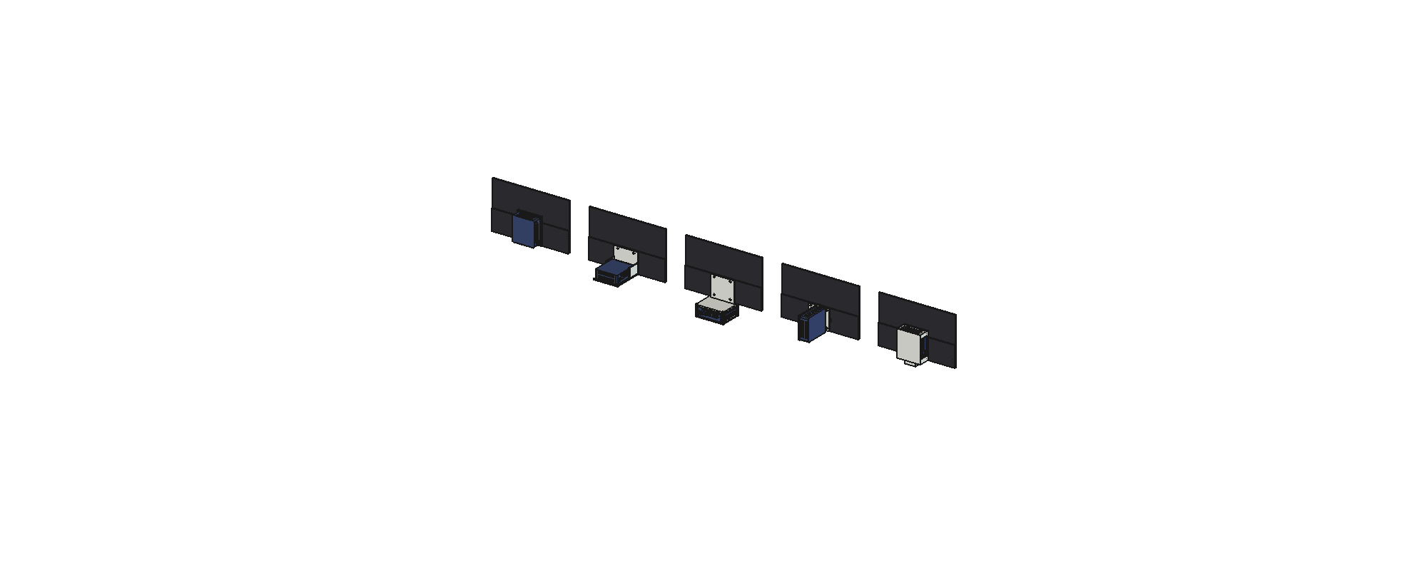
| A Back plate | B Shelf | C Chin | D Fin | E Hub | |
|---|---|---|---|---|---|
| How the PC sits | On its side, flat on the plate, on two shoulder screws in keyholes (as v2) | Lying flat on a shelf at the plate's foot, reaching back | Under the screen, front flush with the screen's face, on a shelf hung from four corner posts | On edge, its base screwed to a fin off the plate, ports down | As A, inside a shell with vent windows and a socket for a stand post |
| PC centre above the screen's bottom edge | 65 mm | 28 mm | −27 mm | 54 mm | 65 mm |
| Combined centre of gravity above the bottom edge | 84 mm | 73 mm | 56 mm | 81 mm | 83 mm |
| Depth from the screen's face | 56 mm | 150 mm | 102 mm | 147 mm | 62 mm |
| Hangs below the screen | No | No | 53 mm | No | 19 mm |
| VESA screws under the PC | All four | Lower two | None | Two | All four |
| Power button | Side | Side | Front, in view | Top | Side, through a window |
| Mount PLA (2 walls, 15%) | 38 g | 69 g | 98 g | 60 g | 76 g |
| Flat, no supports | Plate down; the shelf rises as a 140 mm wall | Needs supports or a split | Plate down; a 6 mm fin 136 mm tall | Two parts |
All five pass the checks: one valid solid each, no overlap with the monitor or the PC, and each fits the A1.
Reading the table
- A and E are the thinnest behind the screen (56 to 62 mm) but put the PC highest. A is the simplest print of the five.
- B puts the PC low and keeps it hidden behind the screen, at the cost of depth.
- C gives the lowest centre of gravity and the power button in view. It hangs 53 mm below the screen, so the screen sits higher on any stand, and it needs supports.
- D is narrow from behind. Its fin could also be where a stand attaches.
From 6: a low centre of gravity does not raise the push to tip by itself. It helps the 10° tilt test. The real gain comes when the stand puts its foot's edges far from the centre of gravity.
A small fix from the checks
In the first build of B and D, one side vent of the PC faced the plate with a 1 to 2 mm gap. The fix was to move the PC 15 mm off the plate. This gap is now a fixed parameter (VENT = 15) in the build script.
The choice
I chose E, the hub. It keeps the PC thin behind the screen, the shell gives a finished device rather than a bracket, and its socket gives every stand one interface to dock into. That makes the stand a separate design problem, which is where 8 Stand v3 starts.