8 Stand v3: the hub and its stands
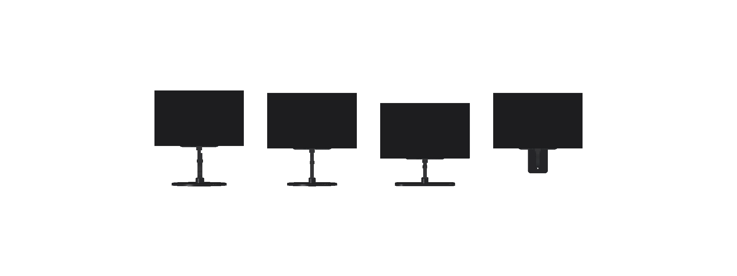
With the hub chosen (7.1), the workstation becomes two problems with one interface between them:
- The hub on the monitor's back. A flat-printed carrier plate on the four VESA inserts holds the PC and carries a docking collar. A cosmetic shell covers both, so from behind it reads as one device, not a bracket.
- The stand, which docks into the collar. Because every stand shares that one interface, I can try several without touching the hub.
The range
| Form | |
|---|---|
| E1 Arc | A bowed fin on a disc, after a reference monitor I liked |
| E2 Column | A straight, tapered fin on a disc |
| E3 Sail | A deep fin with a swept back edge, on a flat foot |
| E4 Wall | A short fin on a wall plate, added later |
The print method drives the design
Each stand is a 14 mm fin printed flat. That follows straight from 5.2:
- Printed flat, the fin's profile lies on the bed, so the screen's bending runs along the layers, not across them.
- A flat print can taper freely in the plane of the bed. The constant-width rule only applies to side prints.
- The heat-set inserts that join the fin to the collar and the foot stay vertical in the print.
The balance check from 6 applies to every stand: on each edge, with the real masses.
- 8.1 The hub: carrier, shell and docking collar.
- 8.2 Three stands: Arc, Column and Sail, with ballast, balance and stiffness.
- 8.3 Printing and iterating: sealing steel in a print, bearing faces, and what the slicer caught.
- 8.4 Finishing the device: cable routes, a TPU pad ring that sets the tipping edge, and vent area.
- 8.5 E4 Wall: the same dock on a wall plate.
- 8.6 Exports and assembly: two hidden export faults, and the assembly sequence.
- 8.7 Where it stands: the final range table, what changed between v1, v2 and v3, the process lessons and next steps.