2.1 Modelling what I have
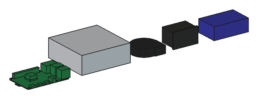
All four concepts are built on one set of reference models: the parts I own, modelled from their makers' drawings. One library, lib/pistack.py, holds them along with the checks and the render code, so a fix to a part shows up in every concept at once.
The parts
| Part | Size (mm) | Source |
|---|---|---|
| Raspberry Pi 4 Model B | 85 × 56 PCB, 1.4 thick; holes 2.7 on 58 × 49, 3.5 in from the edges; USB stacks 16.0 tall, Ethernet 13.5, GPIO header 8.5 | Raspberry Pi mechanical drawing; PCB thickness a common value |
| Mean Well RS-50-5 | 99 × 97 × 36; five terminals along one 97 mm end; two M3 in the base, 55 apart | Mean Well datasheet, case 905B |
| GDSTIME blower | 50 × 51 × 15 with the outlet; outlet on one side, round inlet on top | assumed 5015, to measure |
| IEC inlet | flange 50 × 31; body 47.5 × 27.5, 32 deep | assumed, to check against the one I buy |
| Power hub | 70 × 45 × 25 | space reserved |
The Pi model isn't just a slab. It has the header, both USB stacks, Ethernet, USB-C, both micro HDMI, the audio jack, the SoC with a small stick-on heatsink, and the microSD socket and card underneath. Each sits where the drawing puts it, at the height the drawing gives. That matters, because the boards are packed close in some concepts and the tallest parts set the spacing.
One surprise: plenty of listings give the RS-50-5 as 99 × 82 × 30 mm. Mean Well's own drawing says 99 × 97 × 36. Claude used the drawing, and I'll measure mine to settle it. Every value is marked as drawing, listing or measured, so I know which ones to check with the callipers.
Keep-outs
A component isn't only its body. It needs room around it, so each part has a keep-out solid alongside its body:
- Pi: 2 mm under the board, open round the four holes for the standoffs, and the right-angle USB-C plug: 10 mm out of the socket, cable turned along the board's edge.
- Power supply: 25 mm in front of the terminal block for the leads, and a 5 mm air gap over the top.
- Blower: 10 mm of free air over the inlet.
- Inlet: 15 mm behind the body for the crimped tabs, and room for the plug outside.
- Hub: 15 mm along one long side for the leads.
The checks
Every concept runs the same checks, through one script that rebuilds it in FreeCAD, checks it, writes checks.json and saves the renders.
- Valid solids. Every printed part and every perspex panel is one valid solid with positive volume.
- Bed fit. Every printed part fits the A1 with 6 mm in hand: its two longest sides are 250 mm or less.
- No clashes. Each printed part and panel is tested against every other one, every component and every keep-out, as a common volume. Anything over 0.5 mm³ fails.
- Components in each other's way. Each component against every other component's keep-out.
- Balance. Total mass, the centre of gravity, the 10° tilt test, and the push at the top that tips it over.
- Airflow. The air channel each board gets, and the air speed and temperature rise.
The fourth check wasn't there at first. While laying out B, Claude found that nothing would have caught the inlet's body sitting in the power supply's lead space, because components were only tested against printed parts. It added the check before going on, and reran A to be sure A still passed. It did.
Balance
The tilt test is the self-restoring rule. A stand tilted by an angle stays up while its centre of gravity is still inside its footprint, so for every edge:
where is the distance from the centre of gravity to the edge in plan, and is the centre of gravity's height. A push at height tips it over that edge when:
The masses are guesses until I can slice and weigh things: 46 g per Pi, 330 g for the power supply, 25 g per blower, 30 g for the inlet, 180 g for the hub and the wiring, 1.19 g/cm³ for perspex, and PETG at 1.27 g/cm³ times 0.55, because thin enclosure walls print mostly solid.
Airflow
The two blowers are about 1.8 L/s each in free air (typical for the size, not measured). Pushing through ducts and slots, I've assumed they deliver 2 L/s between them. The temperature rise of the boards' air is then:
with the boards' 33 W at full load, and for air, and the flow in m³/s. So at a 22 °C room the air leaves at about 36 °C. The SoC runs well above its air, and a Pi 4 starts to throttle at 80 °C, so that's workable, but it's not a lot of margin for five boards flat out for hours. The same 13.7 K applies to every concept, because it's the same heat and the same fans. What differs is how each design shares the air out, and whether the power supply's 7 W joins it.
The check also reports each board's air channel (the cross-section the air passes through beside the board) and the mean speed through it. Faster air takes heat off a board better, so a smaller channel isn't a bad thing as long as the fans can still push through it.