3 Round 1
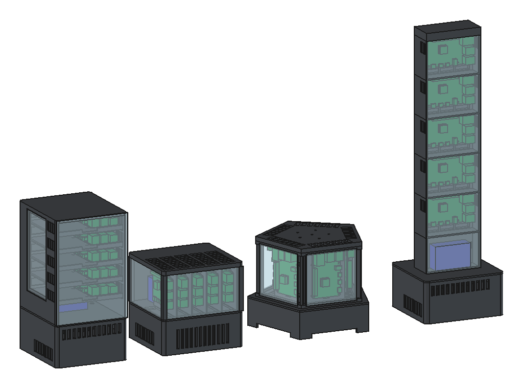
Four concepts, all at the same scale, all built on the same parts, all passing the same checks. Each one has its own post with the engineering: A (3.1), B (3.2), C (3.3) and D (3.4).
| A Sled Tower | B Blade Rack | C Pentagon Column | D Monolith | |
|---|---|---|---|---|
| The idea | Boards flat on sliding trays | Boards on edge, side by side | One board on each face | Five boards in one column |
| Size, W × D × H | 142 × 163 × 277 mm | 160 × 150 × 158 mm | 223 × 212 × 166 mm | 158 × 148 × 531 mm |
| Boards seen | Edge on from the front | Edge on | Face on, all round | Face on, all five from the front |
| Air path | Rear duct, a slot to each tray | Straight up between the blades | Up each face | Rear duct, a slot to each cell |
| Air channel per board | 2,540 mm² | 1,360 mm² | 1,430 mm² | 1,090 mm² |
| Mass (estimate) | 1.74 kg | 1.37 kg | 1.42 kg | 1.56 kg |
| Printed PETG (estimate) | 0.73 kg | 0.43 kg | 0.43 kg | 0.57 kg |
| Tips at | 30° | 46° | 44° | 20° |
| Push at the top to tip it | 4.3 N | 6.3 N | 7.0 N | 1.9 N |
| Prints | 8 | 9 | 5 | 9 |
| Largest print | 142 × 160 × 197 mm | 160 × 150 × 91 mm | 223 × 212 × 51 mm | 158 × 148 × 77 mm |
| Perspex | door and 2 windows | 3 panels | 5 windows | 1 tall front |
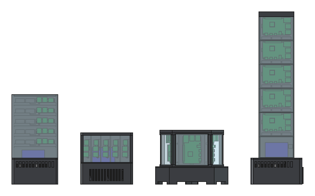
What every base had to solve
The boards were never the hard part. Every concept's base is shaped by three things that have to share a small box: the power supply (99 × 97 × 36 mm), the mains compartment round its terminals, and the inlet, which is about 47 mm deep once its crimped tabs are on. The inlet can't sit in the 25 mm of lead space in front of the terminal block, and the terminal block covers half of the supply's end.
A, C and D solve it the same way: the inlet goes one level up, so its body sits over the terminal zone rather than in it, and the compartment is a closed pocket that runs between the two levels. B solves it by putting the blowers at the front and the power supply behind them, which leaves room at the back right for the inlet.
The other repeated idea is feeding the boards in parallel. If air passes five boards in a row, the last board gets air the first four have already warmed. A and D have a duct up the back with a slot to each board. B and C give each board its own channel from a shared plenum.
What the checks caught
A passed first time. The other three failed their first check run, and every failure was real:
| Concept | What clashed | Overlap | Fix |
|---|---|---|---|
| B | Inlet body against a compartment wall | 639 mm³ | Wall moved 2 mm |
| B | A wall inside the supply's lead space | 144 mm³ | Wall removed, the blower bay wall closes it |
| B | Blade 5 against a corner post | 66 mm³ | Blades start 3 mm further back |
| C | Each corner post in a board's USB-C plug space | 43 mm³, five times | Posts moved out (3.3) |
| D | Power hub against the bay's carrier wall | 1,890 mm³ | Hub moved 0.8 mm forward |
| D | A wall inside the supply's lead space | 72 mm³ | Wall trimmed |
One fault got past the checks. C's plinth is wider than its column, and the gap between them was open to the plenum, so half the air would have blown straight out. No solid overlapped anything, so no check failed. Claude spotted it in the render, because the blue power hub showed through the gap. A check for openings in a plenum would be worth writing.