9.3 How it works
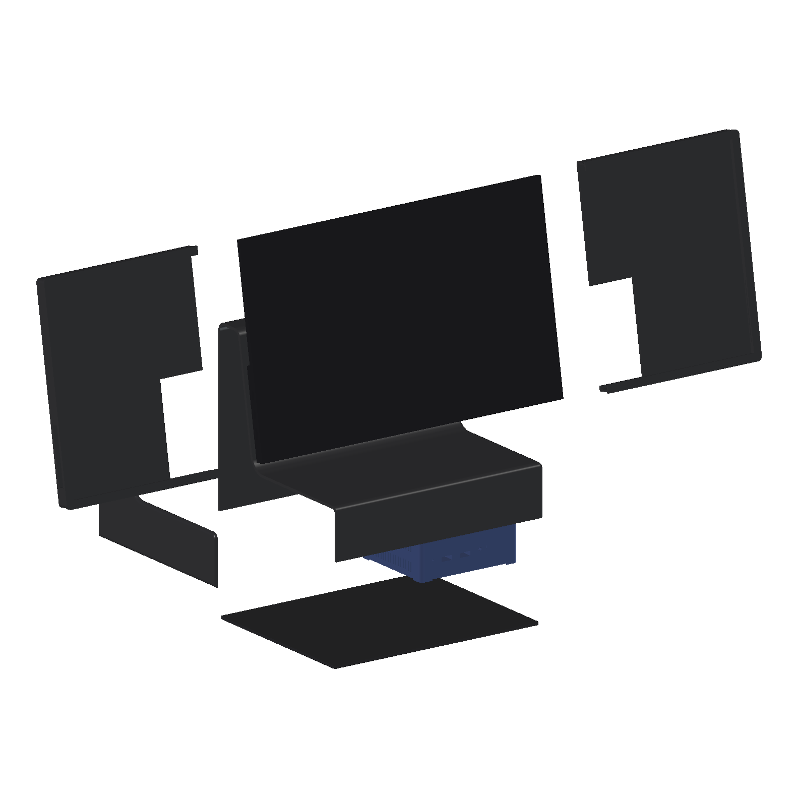
Five printed parts, the monitor, the PC and four screws.
The parts
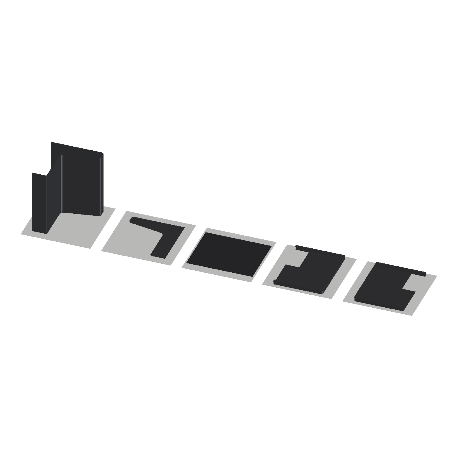
| Part | Size | What it does | |
|---|---|---|---|
| Body | 250 × 200 × 194 mm | On its right side, 246 mm tall | The base and the neck in one shell with 3 mm walls. Holds the PC and the screen. |
| Left cap | 200 × 194 × 3 mm | Flat | Closes the body's open left side, behind a 0.6 mm reveal |
| Floor | 243 × 193 × 3 mm | Flat | Closes the bottom. The PC stands on it. |
| Case, left and right | 182 × 230 × 15 mm each | Back down | Wraps the monitor: back, edges and a 5 mm lip over the front |
The body is the hard one. Printed on its right side, its L-shaped profile lies on the bed and it stands 246 mm tall, 10 mm short of the A1's limit. Every wall is then vertical, the halftone is on the bed, and the neck's bending runs along the layers. The left side has to be open, because it would be a 200 × 194 mm roof at the top of the print, with nothing under it. The bottom is open so the PC can go in. Both close with flat parts.
The screen
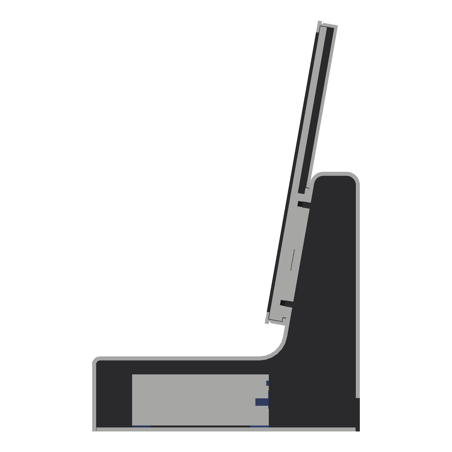
The section is cut 37.5 mm right of the centre, through the PC and the right-hand pair of VESA inserts. Grey is the cut.
The monitor sits in the two case halves. Each half slides on from its side, and they meet on the centre line. In the middle of the case's back there's a 101 × 99 mm window. A 2.8 mm boss on the neck's front face passes through it and bears straight on the monitor's back, round the VESA inserts. So the screen's weight goes from the monitor into the neck without passing through the case.
Four M4 × 10 with washers go in from inside the neck: through the neck's 3 mm wall, through the boss and into the inserts. That clamps 6.6 mm (wall, boss and a 0.8 mm washer) and leaves 3.4 mm of thread in each insert. I measured the inserts' usable depth at 3.6 mm with the test frame, so an M4 × 10 just fits. The neck's face also presses on the case round the window, which is what holds the two halves together.
The case's back face and the neck's front face are the same plane, and the boss face and the monitor's back are another. The checks treat both as contacts, not overlaps.
The PC
The Beelink sits in the base on the floor, front to the front, rear ports to the back. Measured from the model:
| Clearance | mm |
|---|---|
| Behind the rear ports, for plugs and the cables' turn up into the neck | 65 |
| Above the PC, under the base's top | 10 |
| Right-hand vents to the right wall and the halftone | 7 |
| Front to the base's front wall | 27 |
Air comes in through the base and leaves through the halftone on the right (9.2). The intake vents in the floor and the feet that lift it off the desk aren't designed yet.
Balance
The same rule as every stand since 6: push the top edge of the screen and work out what force tips it over each edge.
| Mass | |
|---|---|
| Printed parts (body 491 g, floor 148 g, cap 54 g, case 2 × 117 g) | 0.93 kg |
| Monitor (not weighed yet, as before) | 0.8 kg |
| PC | 0.28 kg |
| Total | 2.01 kg |
The PLA masses assume the 3 mm walls print 85% solid. Thin walls print nearly solid, as v3's shell showed.
The centre of gravity is 135 mm behind the front edge and 127 mm up. The screen's top edge is 307 mm above the desk. For the back edge, 65 mm behind the centre of gravity:
| Edge | Centre of gravity to edge | Push to tip |
|---|---|---|
| Front | 135 mm | 8.7 N |
| Back | 65 mm | 4.2 N |
| Left | 129 mm | 8.3 N |
| Right | 117 mm | 7.5 N |
It passes the 10° tilt test: that needs 22 mm to every edge and the smallest is 65. But the back is weak. Pushing the screen backwards, which is what you do when you tap it or adjust it, tips it at 4.2 N. v3's weakest edge was 5.1 N. The neck and the screen both sit at the back of the base, so the centre of gravity does too. I'll fix this in the next design iteration. The obvious options are steel in the front of the floor, or moving the screen forward.
What the checks cover
check.py runs on the model and writes its results to a JSON file. All of these pass:
- Every printed part is one valid solid.
- No two parts overlap, and nothing overlaps the monitor or the PC.
- The boss touches the monitor's back, and the case touches the neck's face.
- Every part fits the A1's 256 mm cube in its print orientation.
- The screw leaves no more thread in the inserts than they have.
- The 10° tilt test.
Not designed yet
- The joints between the body, the cap and the floor, and their screws.
- Feet, and the intake vents in the floor.
- The lip on the case prints as a 5 mm overhang at the top of the part. It needs a 45° chamfer underneath.
- The cable route from the monitor's left edge into the neck.
- A way to press the PC's power button, or a BIOS setting to start it when the power comes on.
- Balance, as above.
None of it is printed. Next is the design iteration that fixes the back edge, then a slice of the body to see what 246 mm of thin wall costs in time and filament.