1.1 Power and wiring
The wiring is the same for every concept, so it comes first. Only the lead lengths change from one design to the next.
The power budget
| Load | Count | Current each | Total |
|---|---|---|---|
| Pi 4 Model B, all cores flat out, no USB devices | 5 | 1.3 A | 6.5 A |
| GDSTIME blower | 2 | 0.14 A | 0.28 A |
| Total at 5.2 V | 6.8 A, 35 W |
The 1.3 A per board is a design value a little above the commonly published full-load figure for a Pi 4 (about 1.25 A, 6.4 W). Idle is nearer 0.6 A. So the stack uses 68% of the RS-50-5's 10 A flat out, and about a third at idle. Mean Well's derating curve allows the full 10 A up to 50 °C ambient, so there's room.
At 83% efficiency the supply turns about 7 W into heat at full load. Add the boards' 33 W and the box holds about 42 W. That's the number the airflow has to deal with (2.1).
The budget assumes nothing is plugged into the boards' USB ports. Each USB device could draw up to 1.2 A more, so that would need a new budget.
The mains side
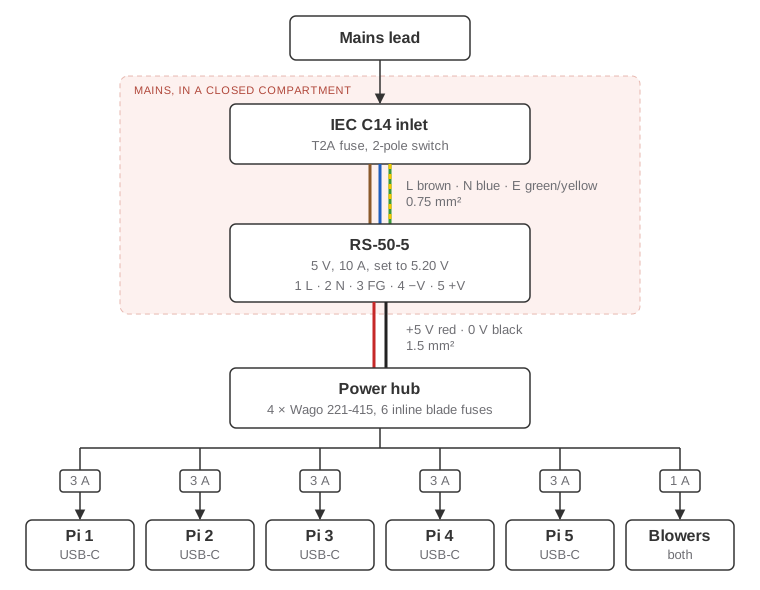
The inlet is a fused, switched IEC C14 panel module: one part gives the kettle-lead socket, a 5 × 20 mm fuse holder and a two-pole switch. I've put a T2A fuse in it. The RS-50-5 takes 0.8 A at 230 V, but its datasheet gives a cold-start inrush of 33 A, and a slow-blow fuse rides through that where a fast one might not. The plug fuse on the lead drops to 3 A.
Three 0.75 mm² wires go from the inlet to the supply's terminals 1 to 3. Fully insulated 6.3 mm spades on the inlet's tabs, bootlace ferrules in the supply's screw terminals. Earth goes to the FG terminal. The supply's metal case is the only exposed metal in the box, so earthing it covers everything. The 5 V output stays floating from earth, as Mean Well builds it.
The terminals and the inlet sit in a closed printed compartment in every concept. Laying that compartment out turned out to drive the shape of every base, which I'll come back to in 3.
Why USB-C pigtails
Each board gets its power through its own USB-C socket, from a right-angle USB-C pigtail: a plug with two bare 20 AWG wires.
- The board's own input protection stays in the path. Feeding 5 V into the GPIO pins skips it.
- The plug is held by a real connector, and the GPIO header stays free.
- A power-only plug has no e-marker chip, so every revision of the Pi 4 accepts it.
- Right-angle plugs keep each lead within 15 mm of the board's edge. Every concept relies on that.
One fuse a board
The RS-50-5 protects itself, but only at 110 to 150% of its rating: somewhere between 11 and 15 A. That's far more than a 20 AWG pigtail should carry for long. So each board's lead gets its own 3 A mini blade fuse, and the fans share a 1 A one. A dead short on one board blows one fuse, and the other four keep running.
The first plan was an automotive 6-way blade fuse block with a negative bus. It's tidy, but it's about 90 × 52 × 30 mm, and it didn't fit the pentagon concept's plinth however Claude turned it. So every concept now uses a small power hub instead: a printed holder with four Wago 221-415 lever connectors (two joined for +5 V, two for 0 V) and six inline fuse holders, about 70 × 45 × 25 mm. Two joined 221-415s give eight ports a side: the supply in, the link between them, five boards and the fans.
Voltage drop
The Pi 4 wants 5.1 V at its socket and flags under-voltage below about 4.63 V. With the supply set to 5.20 V, the drop at full load works out like this, where the round trip is twice the lead length:
| Path | Resistance | Drop |
|---|---|---|
| Supply to hub, 2 × 300 mm of 1.5 mm² at 6.8 A | 0.007 Ω | 0.05 V |
| Fuse and holder at 1.3 A | about 0.03 Ω | 0.04 V |
| Pigtail, 2 × 300 mm of 20 AWG at 1.3 A | 0.02 Ω | 0.03 V |
| Total | about 0.12 V, so 5.08 V at the board |
That's fine. If a board reports under-voltage under load, the trimmer on the supply goes up to 5.25 V.
First power-up
- With no boards and no fans connected, check every mains connection, then fit the compartment cover.
- Switch on and set 5.20 V at the hub with the trimmer.
- Switch off, fit the fans' fuse, check both fans run.
- Fit the boards' fuses one at a time and check each one boots.
- Run all five flat out (
stress-ng --cpu 4) for 30 minutes. Every board should read0x0fromvcgencmd get_throttled(no under-voltage, no throttling), and I'll log each one'svcgencmd measure_temp.